
The My Airborne Rotor v3 (MAR3) Airborne Wind Energy System (AWES) in this video:
…is free and open source. This site provides an overview of the design files and instructional videos that I am publishing to make it as easy as possible for you to make your own.
Overview
To build an AWES we need:
- Lift (to stay airborne)
- a Rotor (to convert the kinetic energy in the wind into mechanical energy)
- a power transmission to the ground aka the “OTS”
- a generator
- And we probably need a control system.
1. Lift
The rotor generates it’s own lift like an autogiro. But it would need an active control system and variable pitch to be able to stay “up”. For now we get around this by suspending the entire system under a pilot kite that provides additional lift and forces the rotor to stay at an elevation angle. I am using a Pilot 50 from David Gomberg in the video:

Sadly (for us) and luckily for David he retired in 2020 – and I do not think that anybody currently makes his kites. But any large & stable kite will do. E.g. the KAP Foil 5.0. If you fly the system at more than 5m/s I would probably use a smaller kite.
2. Rotor
I published all the design details for the rotor a while ago on a site that went down. Luckily I have a PDF copy of it that you can find here. This PDF includes all details needed to build the rotor.
We are currently building a new rotor. Once the design is ready you will find it here.
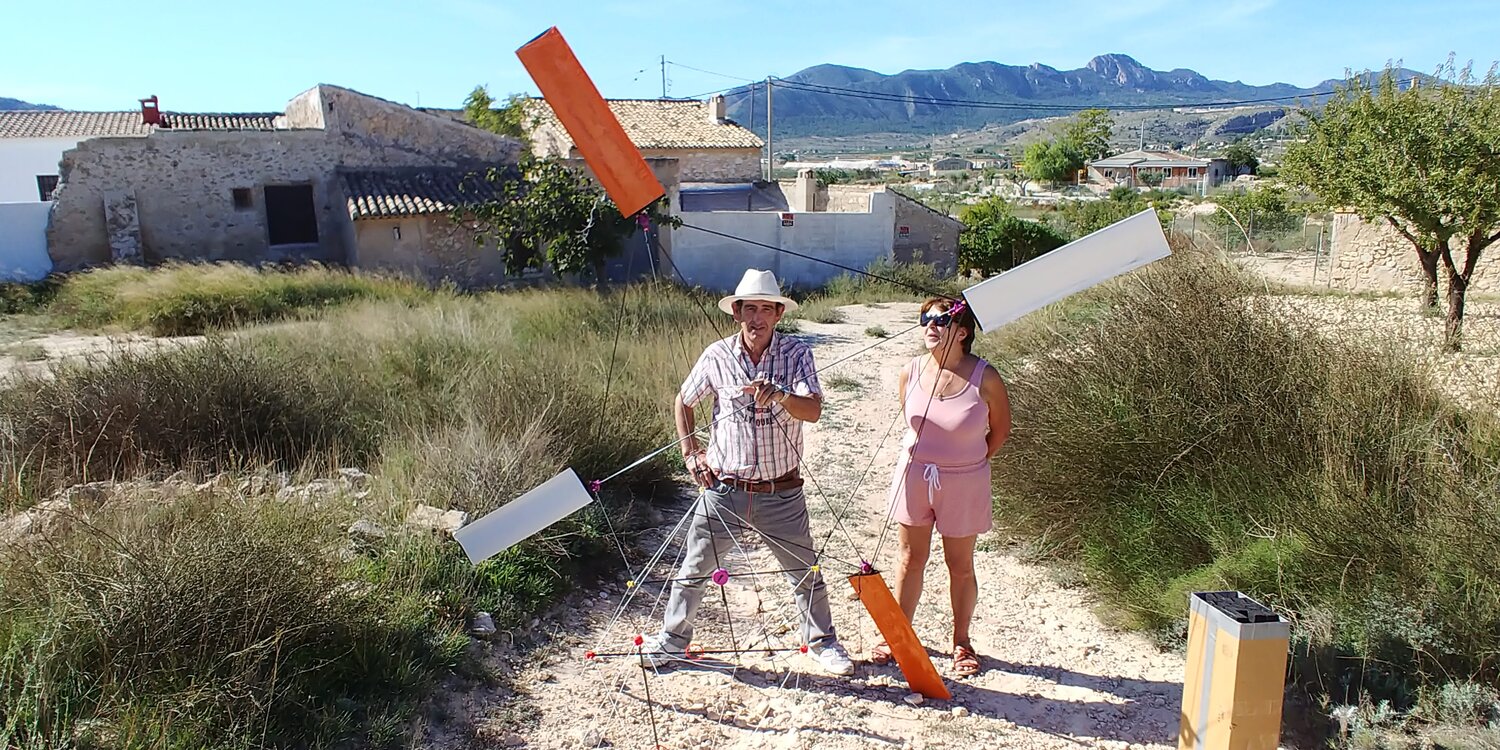
3. OTS (Open Tensegrity Shaft) or the helix
The power from the rotor needs to be transferred to the ground. We use torque which has the advantage of continuous operation over the “lift power” method used by many other systems. It also has a lot less mass in the air and shorter cables than the “drag” method that e.g. Makani/Google have been working on. Since a conventional shaft would be to heavy the system uses as method called Tensile Rotary Power Transmission (TRPT). For lack of a better idea I have called the shaft an “Open Tensegrity Shaft” (OTS). Since the actual power is being transfered through two tethers that form a squared DNA like double “Helix” I often use that term instead. An OTS is as a:
Rotating three-dimensional long structure made of components in compression (struts) and tension (tethers) for the torque based transmission of power.
The OTS consists of two working tethers that provide the actual power transfer (a, b). The working tethers take a shape that closely resembles a double Helix. Two counter helices (a’, b’) can be used in the future to transfer power from the ground to the rotor (e.g. for staying aloft in a lull) and four corner lines stabilise the structure (c1-c4). The struts (S1, S2) are positioned in an angle of 90 degree to each other (which makes S1 parallel to S3). The struts consist of 400mm long carbon fibre tubes with a diameter of 5mm. The distance between two struts is chosen such that they form the opposite edges of a Tetrahedron = 1/sqrt(2) ~70% of the strut length. For no particular scientific reason – just because it feels right.

The work helix tethers are 100kg breaking load ultra-high molecular weight polyethylene (UHMwPE) or how the Koninklijke DSM N.V. likes to call it: Dyneema. Many kite line manufacturers sell the same material under many different brands. For example Cyclone X-trem.
All other tethers have a 50kg breaking load.
To assemble the helix I would recommend building a jig that holds the struts in place while you attach the tethers to the carbon tubes. Something like this:

A good way to attach a tether to a stick (which you will have to do a lot is the Clove hitch aka Webleinstek aka Mastwurf:
4. Generator and base
The generator is integrated into a ground station that needs to:
- Gear up the relatively low Helix RPMs (120RPM) to the higher RPMs (720RPM) needed by the generator
- Track the movement of the kite horizontally and vertically
- Take up the lift and the torque forces
The design of the ground station can be found here.

Most parts are “off-the-shelf” and can be found in the Bill of materials that you can find here.
All flat parts can be made on a gantry CNC machine. Here is how.
5. Control system
As long as there is wind the system is inherently stable – thanks to the pilot kite. We use however an Electronic Speed Controller (ESC) to be able to:
- control the rotor RPMs,
- Smoothly speed up and slow down the rotor
- limit the torque in the helix to the maximum it can handle (25Nm)
The ESC we use ist a VESC 4.12 Open Source Hard&Software by the incredible Benjamin Vedder:

Check out the https://vesc-project.com/ for details.
We have the VESC hooked up to an ESP32 to
- Enrich the data with wind data from an anemometer
- Log data about RPMs, Power, Current etc into a database
- Provide a GUI
- Enrich the data with torque and lift data from load cells integrated into the base station
The PCB design and the source code can be found here.

The control software is not ready yet. In the meantime we have been using the “SF-12-24-A 12V/24V Wind Generator Charge Controller 300W/600W Waterproof Wind And Light Hybrid Controller”.

It works BUT has a build in feature that proved to be fatal for the helix:
This project and its documentation is “work in progress”. If any information is missing, incorrect or outdated please do not hesitate to reach out. I will be more than happy to help out.
Enjoy!